


The pulse voltage control driver circuit is a NE555 timer and a 4017 decade counter. The 555 timer generates pulses at a frequency four times the desired output frequency. For example, if we want an output of 60 Hz, the timer frequency must be equal to 240 Hz (4 * 60 Hz). For an output of 50 Hz, the 555 output is 200 Hz. Here, the combination of R1 and C1 is set to obtain the desired frequency from 1Hz to 60Hz using potentiometer VR1.
The entire circuit is powered by an external 12v 1A adapter that is connected to the device’s on/off switch. The voltage from the switch goes to the LM7809 voltage regulator that is used to protect the 555 and 4017 from voltage spikes and transient pulses that can affect their operation and stability. The output voltage must be 9 V so that we can more easily drive the Mosfets Q1 and Q2.
The CD4017 decade counter is configured so that only its two outputs work. Input pin 14 (clock) is connected via R2 1.2k to output (3) of the NE555 timer. Output pin 2 on the decade counter is connected via R3 100ohm to an LED for visual pulse control. Pin 7 of the decade counter via R4 100ohm triggers (Gate) the mosfet gates.
The MosFet is W7NB80, selected for a power of 6.5A and a voltage of 800V, two are connected in parallel so that the power is 13A and the voltage remains the same. They are cooled by a cooler with a 12v fan so that they work stably without heating up. Diode D2 serves for additional protection of the MosFets from high voltage current and additionally protects the entire circuit for proper operation.
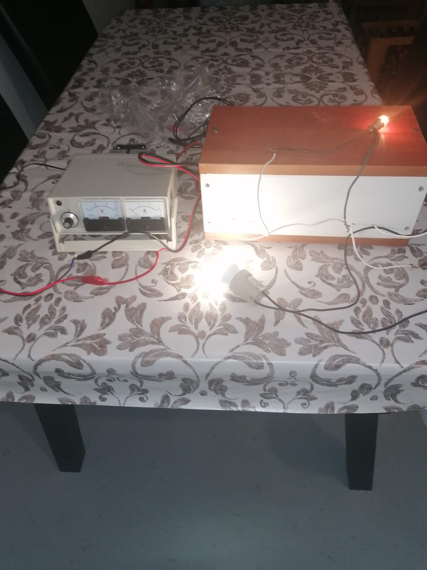
To control the voltage, there is a voltmeter 30v and an ammeter up to 15A for the output power that is provided for that value of the device itself.
